I've been lurking this thread for a while. Many thanks to Grendel for designing this.
I can't find the Teensy anywhere except from PJRC. Is there a UK supplier? Would anyone like to share on the shipping? There's be VAT, a handling fee and duty on top, which is why I haven't jumped in and ordered already.
Posted: Sat Jan 23, 2010 6:38 pm
by londab8
In the end, it was a success. I had a few problems of my own while making it. Once everything was soldered properly (missed 4 pins the first go around!) it ran like a champ. Plugged it in and windows 7 popped up with new hardware found and that was it. Descent 1 and 2 work just fine. Still working on Freespace 2 though. Must be an option thing there.
Overall, very happy with the way it all worked out.
Thanks to Grendel for giving us the opportunity to use our joysticks again the way they were meant to be.
Posted: Sun Feb 14, 2010 3:35 pm
by forlornpants
i finally got around to putting this together and it works great! Thanks so much for posting the info
A little help please --
Posted: Tue Feb 23, 2010 4:30 pm
by bass_player
I stumbled upon this site while looking for a method to make my Sidewinder FF Pro work again.
I am impressed by the clever design, but for the life of me I can't seem to find the link to a schematic.
I think I will build the unit as shown in the pictures above and hope to have the piece parts soon.
Thanks for the quick reply. The circuit diagram and the photos should make this a quick build. I might even try to get a copy of \"Descent\"
Posted: Sun Feb 28, 2010 12:58 pm
by Finishing_Touch
I got the board yesterday and finished building the assembly today. It works perfectly. I can't thank you enough.
Posted: Tue Mar 02, 2010 10:32 am
by pyrlix
I am living here in Germany, and just own a Microsoft Sidewinder FF Pro Gameport Edition, which wasnt cheap here.Now with my newer Computer i've got no Gameport and my Soundcard with Gameport won't work at Windows 7.
I tried several Gameport2USB Converter,but none of them worked.I just cant play Wings of Prey or MSFSX anymore.
Now i found this How2DIY but just cant find the Teensy Board here in Germany.I just need the Contraption for a normal Converter and a Circuit diagram for it.And of course the material list and the software to use it.
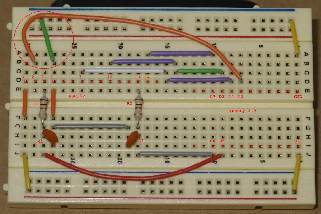
I notice from your photos that the ground pin on the teensy is connected to a floating connector strip on the schmartboard. It also appears that one of the caps is also connected to a floating strip. Is these two grounds deliberately floated, or is there something on the other side of the board that is jumping these connections to the ground pads on the schmartboard?
On my schmartboard (which bears the same part number as the photos) only the three holes in brackets in each of the four corners are connected to the ground plane.
Obviously, the circuit works, but it is a little mysterious to me.
Finally, was there a particular reason to use two jumpers to connect VCC to the d-sub, or was it simply easier to solder that way?
Posted: Tue Mar 02, 2010 4:39 pm
by wolfmanjm
What you can't see as it is covered by a wire is both floating pads are jumpered to the ground rail in both cases, as per the schematic. I'd follow the schematic rather than the photos that can misleading.
As far as I can see there is one jumper from teensy Vcc to a free strip then a jumper from that free strip to the DSUB.
Thanks
Posted: Tue Mar 02, 2010 6:10 pm
by bass_player
I thought there was something hidden in the photo and was prepared to go strictly from the diagram.
I bought the little board that is really for a 25 pin connector, but the 15 pin fits nicely and it gives just a little more room for the wiring.
Unfortunately, I neglected to order the little clips to hold the board together, so I can't complete the circuit until UPS arrives sometime tomorrow.
Thanks again ---
Posted: Wed Mar 03, 2010 5:01 am
by roid
i just noticed this video on Makezine
Circuit Skills: Circuit Board Etching
They basically show you howto etch your own circuit boards. It seems quite easy.
The kit (2 solutions and 2 pre-coated circuit boards) is $46.95 USD from Jameco.com
And extra pre-coated circuit boards are $4.95 USD each.
Assuming the solution in the kit lasts,
- To be below the cost of the breadboard ($13.44) you'd need to make 5 of them ($12.36 each).
- You could print out 13 boards for $101 ($7.80 each)
- Or 33 boards for $200 ($6.07 each)
Though you would still need to drill the holes, and buy & insert the electronics which would be $28.52 per board (not including price of etched board).
If you made 5 boards, the cost would be comparible to the original breadboard version. The etched board would look more professional, would probably be more robust, but would be harder to construct/assemble.
I guess it would be something someone would do if they knew what they were doing, and were making a few of them.
Posted: Thu Mar 04, 2010 3:39 am
by Drakoz
For me I stopped etching PCB's years ago and just send everything to a cheap proto house like Sunstone.com. I don't mean to discourage people etching their own PCB's. I just mean don't be afraid to use the cheap quick turn houses. Most the cost in etching and drilling your own PCB is time, and if you have little of it, it is actually cheaper to get a PCB made by Sunstone.com.
BTW, another alternative to etching is a simple CNC roto-tool type machine to etch the copper off the board with a computer. Search for \"CNC PCB\" on Youtube for many examples. The advantage of such a machine is it's relatively cheap to make, and once it's done, it can both make a PCB with better tolerances than chemical etching, and drill the PCB for you more accurately than you can drill the holes manually. Entry cost is higher, but when done, you have a machine that can do a lot more than make PCB's.
Posted: Sat Mar 13, 2010 10:13 pm
by krod1
Hi All,
I have been using this joystick for 12 years now and really need one of the units. Just went to a new computer and Windows 7 64 with no gameport. I do some soldering but dont think I could pull this one off. If anyone out there has a working unit they want to sell please PM me with a price. Thanks!!!!
Posted: Sun Mar 14, 2010 8:20 am
by krod1
HI Guys,
I just went to the Windows 7 compatiblity center. Believe it or not they say the 3d pro is compatible in windows 7. I just asked them to send me a USB adapter or even some game port drivers that will work. ( I am sure they are already in the mail). I guess all the time and effort all u guys put into this project was for nothing!!! Just call or write microsoft and I am sure they will get an adapter or drivers out to anyone who needs them. (NOT)
Cya
Re:
Posted: Sun Mar 14, 2010 8:36 am
by Floyd
krod1 wrote:I guess all the time and effort all u guys put into this project was for nothing!!!
if you mean the aid this converter provided 3dpro users all these years until now they released win7 were for nothing, then yes.
oh and, please post a picture of your 3dpro plugged into a state of the art notebook (without a docking station, that is).
Re:
Posted: Sun Mar 14, 2010 5:51 pm
by krod1
krod1 wrote:I guess all the time and effort all u guys put into this project was for nothing!!!
I really hope no one thinks I was serious about this quote. It was a jab at MS support. With that said, I still need one of this adapters.
Posted: Sun Mar 14, 2010 11:30 pm
by roid
Your computer's lack of gameport is Microsoft's fault?
is this guy for real?
Re:
Posted: Mon Mar 15, 2010 5:33 pm
by krod1
roid wrote:Your computer's lack of gameport is Microsoft's fault?
is this guy for real?
My computer's gameport has nothing to do with. Windows 7 does NOT support any game port, neither did Vista for that fact. Thanks to Daniel Kawakami Vista 32 bit would support a creative game port but not in Vista 64. So the point being, how can Microsoft say the Sidewinder 3D Pro is compatabile with Windows 7 when Windows 7 does not support any type of 15 pin game port. I hope this helps you understand my point.
Posted: Fri Mar 19, 2010 4:02 pm
by krod1
Thanks Grendel for all the work you and everyone else put in to this project. I got one put together like the one you have in post #26. It only took about an hour and works like a champ. Gonna try one like wolfman's in the near future. Sure is nice to have my 3D Pro back in Windows 7 and Battlefield 2. Thanks Again!!!!
Posted: Fri Mar 19, 2010 9:08 pm
by roid
wow i never realised they removed support in Vista, wtf.
Re:
Posted: Thu Mar 25, 2010 6:55 pm
by Floyd
roid wrote:i just noticed this video on Makezine
Circuit Skills: Circuit Board Etching
They basically show you howto etch your own circuit boards. It seems quite easy.
The kit (2 solutions and 2 pre-coated circuit boards) is $46.95 USD from Jameco.com
And extra pre-coated circuit boards are $4.95 USD each.
Assuming the solution in the kit lasts,
- To be below the cost of the breadboard ($13.44) you'd need to make 5 of them ($12.36 each).
- You could print out 13 boards for $101 ($7.80 each)
- Or 33 boards for $200 ($6.07 each)
Though you would still need to drill the holes, and buy & insert the electronics which would be $28.52 per board (not including price of etched board).
If you made 5 boards, the cost would be comparible to the original breadboard version. The etched board would look more professional, would probably be more robust, but would be harder to construct/assemble.
I guess it would be something someone would do if they knew what they were doing, and were making a few of them.
not worth the effort. the solution fades quickly. depending on the type of solution, you may have to rise the temperature of the solution to work (properly). you already mentioned the drilling. you need extra space to place that stuff to not run it over accidently etc. you have to take the solutions to professional toxic waste disposal. you have extra equipment lying around (some of it contaminated after use), all that goes into the equation.
if double sided, the most disgusting and time consuming part is the connecting of the pads from the upper and lower layer.
find a local PCB maker and pay these 5-10% more, but have it done when it arrives in the mail, with solder resist and tinned pads, edges milled - double sided, if necessary (upper and lower pads are already connected). and it saves your time. you can ask for a quantity rebate too.
afterall, everything you get additionally adds up to about the same price as if you buy it, but you buy without worries
Link is broken
Posted: Thu Mar 25, 2010 8:40 pm
by delveneto
The link posted by Grendel at post # 26 is broken, file \"3DPvertR3_2.zip\". Please, can this be corrected? Thank you.
Posted: Thu Mar 25, 2010 9:39 pm
by Grendel
Ack. I sent an email to the site owner. Meanwhile, anyone who needs the file: send me a PM w/ your email address, I'll send it to you.
Posted: Wed Apr 14, 2010 5:28 pm
by toaste
I happened across this project after picking up the teensy just for use as a dev board, and now my trigger finger's itching! It'll be nice to finally bring the old 3dpro back out of retirement.
Posted: Wed Apr 14, 2010 7:30 pm
by BUBBALOU
just think of all the closets and attics and basements people are going through to find their 3dpros and dust them off after using this tjread as a guide.... Imagine if one of our resident mechwarrior nuggets was to crosspost this thread in the various forums in their communities
Posted: Thu May 20, 2010 2:59 pm
by Grendel
I started a Google Code project for the converter. The hex image is hosted there now. I'll add content as time permits. I'll also change the post on the 1st page as soon RC fixes the boards database..
Posted: Mon Aug 30, 2010 12:00 am
by Mr. Perfect
I don't know if this helps at all, but my Precision Pro actually came with a USB adapter in the box. It has what I'm guessing is a Microsoft part number stamped into it, 98427.
It's awfully small, so it might be simpler to make then what you're building. It doesn't even show up as a device if plugged in by itself.
Posted: Mon Aug 30, 2010 12:23 am
by Grendel
It's a passive part (just a few wires in it) that only works w/ the Precision Pro (part no. X03-57540, product id. starting w/ 85791.) There's a discussion about it here.
Using Windows 7 x64. I can load the Blink slow and Blink fast to the Teensy 2.0 no problem. When I load 3DProR3.hex the led just flashes continuously (fast).
Ive tried with and without a SW 3d Pro connected, any ideas?
Two differences with my build afaik:
- I used a bare DB15 Female socket and soldered the wires too it, connected them in a line as per the numbers (1,2,3,4,7,10,13,14) in the diagram above
- I broke a pin in the small bridging socket on the breadboard, in the images its on the far left, position E30.. I connected F30 to C30 instead, ok I assume?
Posted: Sat Dec 18, 2010 8:36 pm
by motoxbudd
nice forum guys
/me fellow oldskool hardkore descenter.
i just got a brand spankin new, still in sealed box, 3d pro from ebay. gotta love the place. figured it was gonna be a task to get it workin in win7, but i didnt care.
had good reviews on amazon, people say it works good. so i bought it. and it does work! just plugged it to my sw3dp to my win7x64 macbook pro, and poof, drivers installed.
few probs tho. tried all combinations of switch settings on adapter and bottom of sw. hat switch left dont wanna work (up/down/right works). base buttons dont work, but i dont care. what is the big prob is z-axis/twist/rudder works in windows settings, but it dont work in either descent or forsaken. forsaken recoginizes there is a third axis, but it dont do nothin when i twist.
ill post again if i find a fix.
-moto
Posted: Sun Dec 19, 2010 5:57 am
by mattsimis
Presumably it doesnt work fully as the SW3dPro used Midi functions to get the full functionality (IRC) and that adapter explicitly states it doesnt support such functionality.
Surprised it worked at all though, good feedback!
Posted: Sun Dec 19, 2010 8:58 pm
by Grendel
The SW3DP does work w/ certain game port adapters. It will run in analog emulation mode only tho. Full functionality is only possible w/ a native game port and W98/95/NT/XP or the 3DP-Vert USB converter.
Posted: Wed Jan 12, 2011 3:07 pm
by belboz
Quick question. Getting ready to build this on a breadboard.
I looked at these two circuits posted by Grendel and noticed a difference in the two.
On the first one IMG_0553 pin 3 on the 15pin connector is connected to B4 on the Teensy (obviously going through the resistor). Pin 13 on the 15 pin goes to B5 on the Teensy.
On the second image below (IMG_0083x) pin 3 of the 15 pin goes to B5 on the Teensy. Pin 13 of the 15 pin goes to B4 on the Teensy.
I am curious which is correct? Or if maybe a software change occurred which needed that change.
p.s. I did notice rhulasi asked about this difference in the two design images, but I didn't see an answer. It looks like switching these two would only effect the X and Y axis being switched from one design to the other.
The schematic wolfmanjm posted looks to follow the earlier design posted on Oct 2nd by Grendel. But the latter posting by Grendel on Oct 23rd looks to have the sources to B4 and B5 switched.
Minor in the grand scheme. I can build it one way and just switch the two wires if I need to, but was curious which design is right.
Posted: Wed Jan 12, 2011 4:37 pm
by Grendel
The X & Y lines are triggered at the same time to signal the stick to send data -- doesn't matter what way round they are connected.
Posted: Wed Jan 12, 2011 5:41 pm
by belboz
Thanks for the quick feedback. Going to build one tonight or tomorrow. Will post the results when I do!


